Air Intake & Airflow Protection
MACROCORE™
Engine air-intake protection architecture integrating media, capacity, restriction and sealing.
MACROCORE™ is the ELIMFILTERS architecture for engine air-intake protection. It integrates media configuration, contaminant-holding capacity, restriction control, and sealing integrity according to airflow demand and operating conditions.
01 /
Contamination Modes Controlled
Airborne particulate contamination
HOW IT WORKS
How MACROCORE™ Works
An engine draws in a very large volume of air, and whatever dust that air carries goes where the air goes. Mineral dust is hard: once past the air cleaner it abrades piston rings, cylinder liners, valves and turbocharger parts, and much of it ends up suspended in the engine oil, where it keeps wearing the engine from inside. MACROCORE™ is the ELIMFILTERS architecture for the engine air-intake elements, combining media configuration, dust-holding capacity, restriction control and sealing integrity.
The primary element does the main work. Its pleated media presents a large surface to the incoming air, and the dust is held on and within its upstream face. As dust builds up, it forms a layer that itself takes part in the capture, while the resistance to airflow, the restriction, rises gradually. The restriction indicator on the clean side reads that rise, which is why service decisions should follow measured restriction rather than the element's appearance: an element that looks dirty may still have useful capacity, and opening the housing more often than needed is itself a contamination risk.
Inside the primary sits the safety element. It is not the main filter; its job is to keep the clean side of the housing closed while the primary is out at service, and to stop dust if the primary is damaged. A dirty safety element is therefore a symptom: it means something upstream of it has failed.
Elements only protect the engine if the whole clean-air boundary is sealed: housing, seals, cover, clamps and the duct to the engine. A high-capacity element cannot compensate for an unsealed joint downstream of it; the housing and sealing side is governed by INTEKCORE™. ISO 5011 provides the laboratory framework for evaluating an air cleaner, and published values belong to the tested element and housing, never to the technology as a single value.
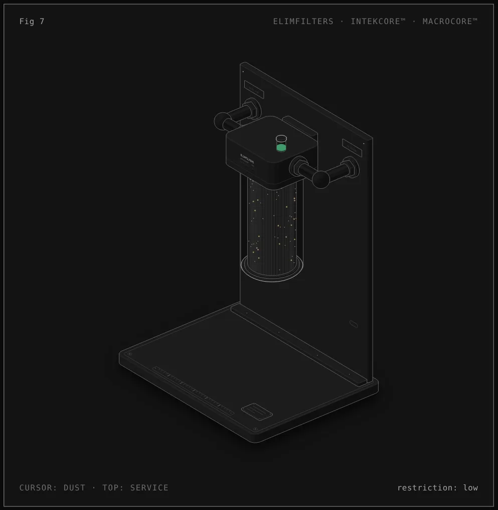
Reading the figure: Primary and safety elements in the air cleaner
- Inlet duct. Dirty air enters the housing through the duct on the left. Moving the cursor sideways changes how much dust the air carries.
- Housing in section. The front of the housing is cut away so the elements can be seen; only its back wall is drawn.
- MACROCORE™ primary element. The air crosses the pleated primary, which holds the dust on its pleats. The dust builds up as a layer on the upstream face.
- Safety element. Inside the primary, the safety element is the last barrier before the clean side.
- Outlet to the engine. Clean air leaves through the duct on the right toward the engine. Everything downstream of the elements has to stay sealed.
- Restriction indicator. On the head, the indicator rises as the primary loads; the readout shows the restriction as low, medium or high.
- Service. Moving the cursor to the top, or pressing E, runs the service: the cover comes down and the primary comes out, while the safety element stays in place and keeps the clean side closed. A new primary goes in and the restriction returns to low.
What each component does
- MACROCORE™ primary element
- The pleated media that holds the dust. Its configuration and dust-holding capacity are matched to the engine's airflow and the dust environment.
- Safety element
- The inner element that stays in place at service and backs up the primary. It is replaced as the engine maker specifies and is never cleaned.
- Element seal
- Seals the element against the housing so no air can pass around the media. It is part of the clean-air boundary.
- Restriction indicator
- Reads the resistance to airflow on the clean side and shows when the primary has reached its service point.
- Housing and cover (INTEKCORE™)
- Hold the elements in the designed position and close the dirty side from the clean side.
- Inlet and outlet ducts
- Bring dirty air in and take clean air to the engine. Every joint after the elements must be sealed and clamped.
- Pre-cleaner (where applicable, not drawn)
- In very dusty duty, removes part of the dust before the air reaches the primary, extending its service life.
Service sequence
- Service the primary when the restriction indicator reaches the limit set by the engine maker, or as its schedule specifies, not by appearance.
- With the engine stopped, clean around the cover before opening it so no dust falls into the housing.
- Remove the cover and the primary carefully, without knocking dust off toward the clean side. Leave the safety element in place.
- Wipe the dirty side of the housing and check the sealing surfaces. Look at the safety element without removing it: if it is dirty, find the leak before fitting a new primary.
- Fit the new MACROCORE™ primary approved for that housing, seat it fully and refit the cover with its latches.
- Reset the restriction indicator and check the duct, clamps and joints between the air cleaner and the engine.
- Replace the safety element as the engine maker specifies; never clean it or reuse it.
Diagnosis in the circuit
Restriction rises much faster than expected
The dust load is heavier than the selection assumed, the pre-cleaner (if fitted) is not working, or the element's capacity does not suit the environment. Review the selection rather than shortening intervals indefinitely.
Dust on the clean side or on the safety element
Something upstream has failed: an element not seated, a damaged seal or element, or a deformed housing or cover. Inspect the whole clean-air boundary.
Low restriction but signs of dust in the engine
Oil analysis showing dust, or abnormal wear, with a clean-looking element points to a leak after the filter: ducts, clamps, joints or the outlet seal.
The indicator does not move or reads erratically
Check the indicator and its connection to the clean side before trusting or replacing the element.
Wet or oily media
Water or oil soaking the media raises restriction and can damage it. Check the position and protection of the air inlet.
02 /
Application Selection
Select the intake architecture from the engine airflow requirement, housing geometry, dust concentration, duty cycle and acceptable restriction progression. The review must cover the complete clean-air boundary: inlet routing, pre-cleaning where applicable, primary element, safety element, seals, clamps and service indicator. A high-capacity element cannot compensate for a damaged housing or an unsealed joint, and a low initial restriction is not sufficient if dust capacity is inadequate for the operating environment. Service decisions should follow measured restriction and inspection of the intake path rather than appearance alone.
Evidence Boundary
MACROCORE™ defines an application architecture, not one universal efficiency, dust capacity or service interval. ISO 5011 provides the relevant laboratory framework for product-level air-cleaner evaluation, but published values must remain tied to the tested element and housing configuration. Final validation requires the engine maker's airflow and restriction limits, the installed housing, the contaminant environment and approved ELIMFILTERS product evidence.
02 /
Protection Systems
COMPLEMENTARY TECHNOLOGIES