Fuel Cleanliness Protection
TURBOCORE™
Turbine-style fuel/water separation architecture reserved for approved FH and FG series systems.
TURBOCORE™ is the ELIMFILTERS turbine-style fuel/water separation architecture reserved exclusively for approved FH and FG series systems. It addresses fuel cleanliness and water management within the approved turbine separator configuration while remaining distinct from HYDROCORE™, which governs standard non-turbine separators. Product-level efficiency, water-separation performance, capacity and service intervals require validated application-specific evidence.
01 /
Contamination Modes Controlled
Fuel particulate contamination
Water contamination in approved FH and FG turbine-style separator systems
HOW IT WORKS
How TURBOCORE™ Works
TURBOCORE™ is the ELIMFILTERS architecture for turbine-style FH and FG fuel/water separation systems. Like a standard separator it removes water and solids from diesel before they reach the injection system, but it does so in stages, and the first stage needs no media at all: it uses the fuel's own flow.
In the first stage, the fuel enters the housing and is directed onto a fixed turbine deflector. Its helical vanes turn the incoming flow into a swirl; nothing rotates. The swirl centrifuges the fuel, so water and the larger solid particles, which are denser than diesel, are thrown out to the wall, slide down and settle at the bottom of the bowl. A large share of the contaminant load is removed here, before the fuel ever reaches the element.
The following stages take place in the replaceable element, which receives fuel already relieved of the free water and the heavier solids and holds what remains. Because the bowl stores the separated water, draining it is part of how the system works: the water has to be released before it reaches the mark, as with any separator.
A turbine-style separator is selected and serviced as a complete approved system: housing size, dedicated element series, bowl and drain arrangement, matched to the fuel flow it has to handle. Standard spin-on or cartridge separators work on a different principle and belong to HYDROCORE™; their logic and parts are not substituted here, even when dimensions look similar.
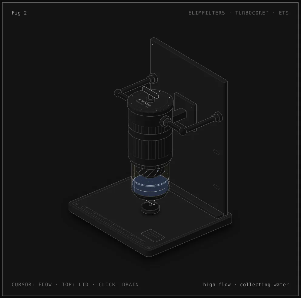
Reading the figure: Turbine-style housing with fixed deflector
- Inlet and outlet. The fuel enters and leaves through the fittings on the side of the cast housing, which is clamped to a wall bracket. Moving the cursor sideways changes the fuel flow through the housing.
- Fixed turbine deflector. Seen through the transparent bowl, the helical vanes of the deflector turn the flow into a swirl. The dashed rings show the fuel turning below it; nothing in the housing rotates.
- Centrifugal separation. The blue drops are water and the dark dots solid residues: being denser than diesel, they are thrown to the wall of the bowl and settle at the bottom.
- Drain. When the water reaches the mark the readout says so. Clicking the figure, or pressing the space bar, opens the drain and releases the water into the cup.
- Lid and element. Moving the cursor to the top, or pressing E, lifts the lid with its T-handle and draws the replaceable element out of the housing: this is the service position. Housing, bowl and deflector stay in place.
What each component does
- Fixed turbine deflector
- The first separation stage. Its helical vanes turn the incoming fuel into a swirl that throws water and heavier solids to the wall of the bowl. It has no moving parts and is not a service part.
- Transparent bowl
- Collects the separated water and residues and lets the operator see the level against the mark.
- Drain
- The valve at the bottom of the bowl. Opening it releases the collected water; it has to be closed again and checked for leaks.
- Replaceable element
- The following separation stages. It belongs to the dedicated series for the housing and comes out through the lid at service.
- Lid with T-handle
- Closes the top of the housing with its bolt circle and seal. Lifting it gives access to the element without disturbing the lines or the bowl.
- Finned cast housing, clamp and bracket
- The permanent body of the system, held to the bracket by a clamp band. It carries the inlet and outlet and is not replaced at service.
Service sequence
- With the engine off, open the drain and release the collected water into a container. Dispose of it as fuel-contaminated waste.
- Confirm that the replacement element belongs to the dedicated series for that FH or FG housing; a standard element is not a substitute.
- Remove the lid and withdraw the used element. Inspect the lid seal and the element seals, and replace them with the ones supplied.
- Fit the new element in the correct orientation, so the intended flow path through the stages is preserved.
- Refit the lid, tighten it as the equipment maker specifies, and refill and prime the system following its service procedure.
- Start the engine and check the lid, the drain and every fitting for leaks. Confirm the drain is closed.
Diagnosis in the circuit
The water reaches the mark again soon after every drain
The separator is doing its job and reporting what the fuel carries. Look upstream: tank condensation, water in deliveries, storage and transfer practices.
Water found downstream of the housing
Check whether the drain was overdue, whether the element is the correct dedicated series and fitted in the right orientation, and whether the internal seals are intact.
Restriction rises with little water in the bowl
The element is loading with what the first stage did not remove. Consider fuel quality and low-temperature waxing before changing the maintenance interval.
Air in the system or a fuel leak after service
Check the lid seal and its tightening, the element seals and the drain. On the suction side a poor seal draws in air rather than leaking fuel.
Dark sludge at the water–fuel boundary in the bowl
A sign of microbial growth. It has to be treated in the tank and fuel system; the separator only shows it.
02 /
Application Selection
Turbine-style separation must be selected as a complete approved FH or FG system, including the housing size, dedicated element series, bowl and drain arrangement, fuel-flow requirement and available service space. Review the contamination source and water-management practice as well as the separator itself; repeated water accumulation can indicate storage, transfer or tank problems that require upstream correction. During service, the correct internal seals, element orientation and drain condition are essential to preserve the intended flow path. Standard spin-on or cartridge separator logic should not be substituted merely because external dimensions appear compatible.
Evidence Boundary
TURBOCORE™ is restricted to approved FH and FG turbine-style systems and their dedicated replacement architecture. It does not provide a universal water-separation efficiency, particle rating, capacity or service interval. Every performance statement must be supported by the validated housing-and-element configuration and applicable test evidence. Standard non-turbine separators remain within HYDROCORE™ scope.
02 /
Protection Systems
COMPLEMENTARY TECHNOLOGIES