Hydraulic Protection
NANOFORCE™
Hydraulic-filtration architecture for fluid cleanliness around pump, valve and actuator tolerances.
NANOFORCE™ is the ELIMFILTERS hydraulic-filtration architecture developed to maintain fluid cleanliness around the tolerance requirements of pumps, valves, actuators and precision hydraulic components. Media and element construction are selected according to the required cleanliness target, critical particle size, system flow, pressure, fluid viscosity and operating duty. This engineering flexibility allows filtration to be configured for pressure-line, return-line and approved offline applications. Product-level efficiency, Beta performance, contaminant capacity and pressure ratings must be supported by validated data under the applicable test standards.
01 /
Contamination Modes Controlled
Hydraulic-fluid particulate contamination
HOW IT WORKS
How NANOFORCE™ Works
Hydraulic pumps, valves and actuators work with very close internal clearances, and the fluid that moves them also lubricates them. Hard particles in the fluid wear those surfaces, and fine particles can pack into the clearances of a valve spool until it responds slowly or sticks. NANOFORCE™ is the ELIMFILTERS hydraulic-filtration architecture that keeps the fluid clean enough for the components it serves.
Hydraulic filtration starts from a cleanliness target, not from a filter. ISO 4406 provides the cleanliness-code framework for expressing how clean the fluid has to be, and the target is set by the most contamination-sensitive component in the circuit. The filter is then sized and positioned to hold that target against the contaminants that keep entering: through reservoir breathers, during filling, past cylinder rods and during maintenance, plus the particles the system generates itself.
Where the filter sits changes what it has to withstand. A pressure-line filter, the one in the figure, sits right after the pump and protects the valves downstream; it carries full system pressure and pressure peaks, so its housing and element must be built for that duty. A return-line filter sits where the fluid comes back to the reservoir at low pressure, capturing what the circuit picked up before it mixes with the stored fluid. An offline filter has its own pump and cleans the reservoir continuously, independent of the machine's duty cycle. Because the duties differ, elements are never interchanged by dimensions alone.
Element performance under the ISO 16889 multi-pass framework, collapse strength, bypass arrangement and pressure ratings belong to each validated product and its circuit, never to the technology as a single value. In service, trending particle counts and the pressure difference across the element says more about the system than replacing elements by appearance or a generic hour interval.
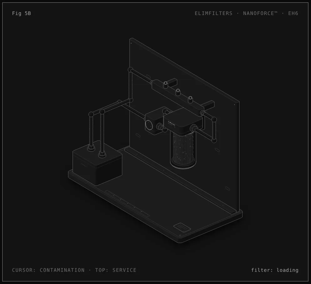
Reading the figure: Pressure-line spin-on in the hydraulic circuit
- Reservoir. The fluid rests in the reservoir on the bench, with the suction and the return on top. Moving the cursor sideways changes how much contamination the fluid carries.
- Pump. The pump draws the fluid through the suction line and sends it under pressure toward the filter head.
- NANOFORCE™ pressure-line spin-on. All the pump flow crosses the pleated NANOFORCE™ element, drawn in section, where the particles are held. The readout shows the filter's load.
- Control-valve block. Downstream of the filter, the valve block with its spool caps along the top receives fluid that has just been cleaned: these close-tolerance spools are the components this position protects.
- Return. From the valves, the fluid goes back to the reservoir through the return line. In a real machine, a return-line filter would sit on this line.
- Service. Moving the cursor to the top, or pressing E, runs the service: the spin-on is replaced and the new one goes on clean. Head, pump and valves stay in place.
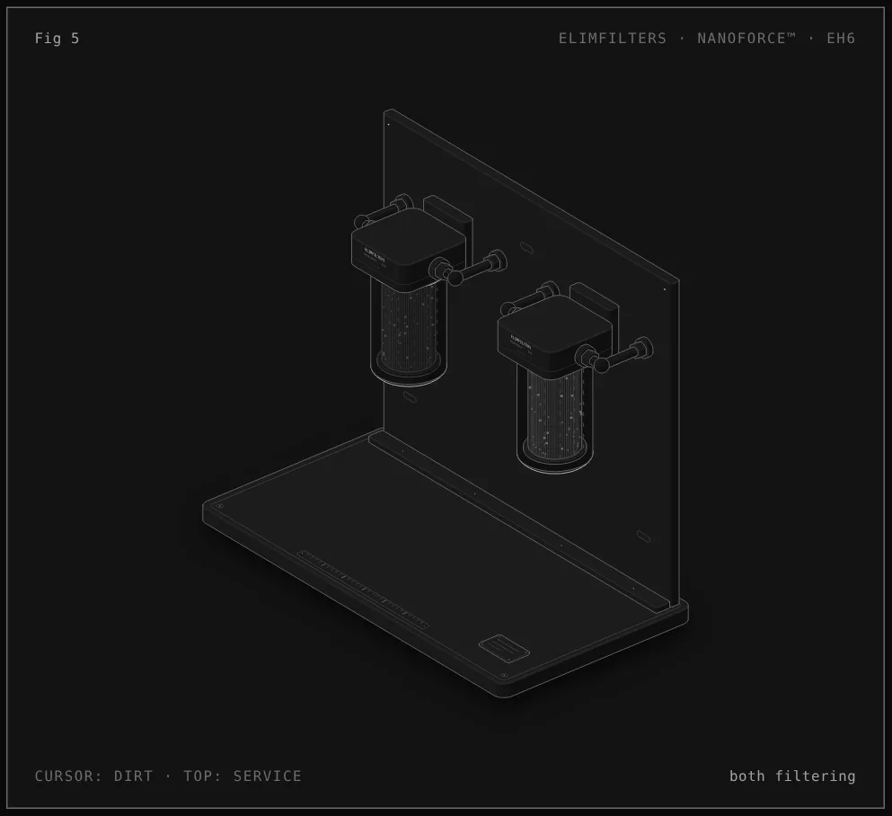
Reading the figure: Spin-on and cartridge formats
- Heads on the bracket. Both filters hang from a fixed head with an inlet and an outlet port. The head belongs to the equipment and is never replaced at service.
- Left: spin-on. The pleated NANOFORCE™ element is sealed inside its own can, which screws onto the head.
- Right: cartridge. A permanent bowl closes against the head and holds a pleated NANOFORCE™ element that is replaced on its own.
- Flow. In both formats the fluid enters through the head, crosses the pleated media, where the particles are held, and leaves through the head toward the circuit. The filtration principle is the same.
- Service. Moving the cursor to the top, or pressing E, runs the service: the spin-on comes off whole, can included; on the cartridge the bowl drops, the element is changed and the same bowl goes back.
What each component does
- Pleated NANOFORCE™ element
- The filtration media, folded into pleats so a large media area fits in a compact element. Its construction is matched to the cleanliness target, flow, viscosity and the pressure duty of its position.
- Filter head
- The fixed mount with the inlet, the outlet and the sealing face. In a pressure-line position it is part of the pressure-rated assembly and has a defined flow direction.
- Spin-on can
- A sealed metal can that contains the element and screws onto the head. Element, can and gasket are replaced together.
- Cartridge bowl
- In the cartridge format, the reusable housing around the element. It comes off at service and is refitted with the new element and its new seals.
- Pump
- Draws fluid from the reservoir and delivers the flow and pressure the circuit works with.
- Control-valve block
- Directs the fluid to the actuators. Its spools work with close clearances, which makes it one of the most contamination-sensitive components in the circuit.
- Reservoir, suction and return
- The reservoir stores the fluid and lets it settle; its breather and filling point are common entry paths for contamination.
- Bypass valve and differential-pressure indicator (where fitted, not drawn)
- The indicator shows how much the element restricts the flow; a bypass, where the design includes one, protects the circuit when that restriction becomes too high. Both belong to the approved housing.
Spin-on and cartridge formats
Spin-on. The element is built into its own sealed can. Service is quick and closed, which also helps keep dirt out of the circuit during the change; the complete can is discarded.
Cartridge. The housing is a permanent, often pressure-rated part of the equipment and only the element is replaced. It asks more of the technician: the housing has to be clean, the seals supplied with the element fitted, and the element seated correctly so no fluid bypasses the media.
Which one applies. The format is set by the approved housing and its position in the circuit. The replacement is chosen for that position, pressure duty, flow direction and bypass arrangement, never by external dimensions alone.
Service sequence
- Stop the machine and relieve the pressure in the circuit, following the equipment maker's procedure, before opening any filter.
- Confirm that the replacement is the NANOFORCE™ element approved for that position and housing, including its pressure duty, flow direction and fluid compatibility.
- Work clean: wipe the head and the surrounding area, keep the new element in its packaging until fitting it, and cap any open port.
- Spin-on: remove the filter, check that the old gasket came off with it, clean the sealing face, lubricate the new gasket with clean system fluid and tighten as specified. Cartridge: remove the bowl and element, clean the housing, fit the new element with its new seals and refit the bowl.
- Top up only with filtered fluid, bleed the air as the equipment procedure specifies, then run the system and check for leaks.
- Record the differential-pressure reading or the particle count after service, so later readings can be compared as a trend.
Diagnosis in the circuit
Elements load much faster than before
Look for new ingression: reservoir breather, filling practice, cylinder rod seals and wipers, maintenance cleanliness, or a component that has started to wear.
The indicator shows high restriction at cold start and clears when warm
Thick cold fluid raises the pressure difference without the element being loaded. Read the indicator at operating temperature before deciding on a change.
Particle counts stay above target although the filter is changed on time
Review whether the position and rating suit the most sensitive component, whether a bypass is leaking, and whether ingression exceeds what the filter can hold; an offline filter may be part of the answer.
Valves respond slowly or stick
Fine particles may be packing into the spool clearances. Check the cleanliness trend at the valves, not only the condition of the filter.
A deformed or collapsed element is found at service
The pressure difference exceeded what that element was built for: check that it is the correct element for the position, the bypass function and the change interval.
02 /
Application Selection
Hydraulic filtration must be placed and sized around the most contamination-sensitive component, the target cleanliness code, circuit flow, operating pressure, fluid viscosity and expected ingression rate. Pressure-line, return-line and offline positions impose different structural and differential-pressure duties, so elements should not be interchanged by dimensions alone. The review should include reservoir breathers, fill practices, cylinder exposure and maintenance cleanliness because filters cannot offset uncontrolled ingression indefinitely. Trending particle counts and differential pressure is more informative than replacing elements on appearance or a generic hour interval.
Evidence Boundary
NANOFORCE™ does not assign one Beta ratio, micron rating, collapse strength, pressure limit or service life to every hydraulic element. ISO 16889 and ISO 4406 provide performance and cleanliness frameworks, but claims must remain tied to validated product data and the actual circuit. Final selection requires the approved housing, flow direction, bypass arrangement, fluid compatibility and equipment cleanliness target.
02 /