Air Intake & Airflow Protection
INTEKCORE™
Air intake housing technology for controlled airflow and sealing integrity.
INTEKCORE™ integrates housing geometry, element retention and sealing to preserve the protected intake boundary.
01 /
Contamination Modes Controlled
Unfiltered-air bypass risk
HOW IT WORKS
How INTEKCORE™ Works
An air filter element only protects the engine if every bit of air passes through it. INTEKCORE™ is the ELIMFILTERS architecture for the air-intake housing: the geometry, element retention and sealing that keep the dirty side and the clean side separated all the way to the engine. A leak anywhere after the element is worse than a weak element, because the air that enters there is not filtered at all.
The housing does several jobs at once. It holds the elements in their designed position against vibration and handling; its geometry and the cover deliver the compression the element seal was designed for; it separates the incoming dirty air from the clean outlet; and it carries the tap for the restriction indicator. Deformed covers, damaged threads, missing latches or a cracked body can open a path around the element even when the media itself is intact.
The clean-air boundary does not end at the housing. The clean-air duct, its couplings and clamps, and the restriction-indicator connection are all part of it: contamination can enter anywhere downstream of the filter. Each element change is also a moment when the boundary is opened, so the housing has to be inspected every time it is closed again.
A replacement element has to preserve the designed seating and seal compression, not just match the external dimensions. ISO 5011 testing is meaningful only for the evaluated air cleaner configuration, and product claims stay tied to the approved housing, element and operating condition. The elements themselves are governed by MACROCORE™.
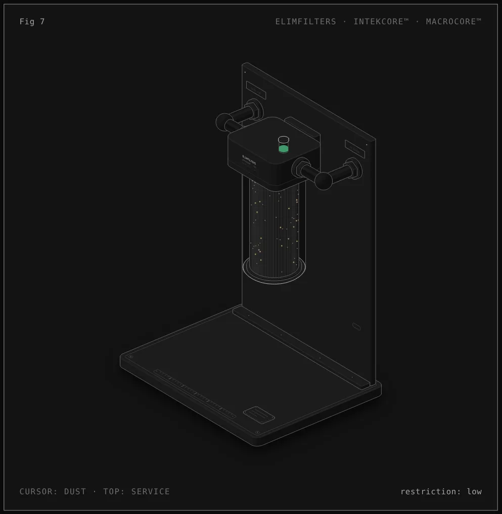
Reading the figure: Air cleaner housing, ducts and restriction indicator
- Head. The cast head, bolted to the wall through its ears, carries the inlet, the outlet and the restriction indicator. It is the fixed top of the housing.
- Dirty side. Dirty air enters through the inlet duct on the left and fills the space around the primary element. Everything on this side may carry dust.
- Housing body. Drawn in section, with only its back wall shown, the housing keeps the elements in place and separates the dirty side from the clean side.
- Cover and latch. The cover closes the bottom of the housing and holds the primary up against the head, so the element seal is compressed as designed.
- Clean side and outlet. Clean air leaves through the outlet duct on the right toward the engine. Any opening on this side lets unfiltered air in.
- Restriction indicator. Its tap reads the clean side; it rises as the elements load and is only accurate if the clean side is sealed.
- Service. Moving the cursor to the top, or pressing E, runs the service: the cover and the primary come off, while the head, housing, ducts and the safety element stay in place and the clean side stays closed.
What each component does
- Head
- The fixed casting that mounts the air cleaner and carries the inlet, the outlet and the indicator connection.
- Housing body
- Holds the elements in their designed position and separates the dirty side from the clean side. Cracks or deformation can open a bypass.
- Cover with latch
- Closes the housing and delivers the element's seal compression. It has to close fully without force; if it does not, the element or the cover is wrong or damaged.
- Seal interfaces
- The surfaces where the element seals against the housing. They must be clean and undamaged at every service.
- Clean-air duct, couplings and clamps
- Carry filtered air to the engine. They are part of the clean-air boundary and a common source of leaks.
- Restriction indicator and its tap
- Show the restriction on the clean side; a blocked or disconnected tap gives a false reading.
- Mounting bracket
- Holds the air cleaner against vibration; a loose mounting can damage the housing and the seals.
- Dust evacuator valve (where fitted, not drawn)
- On housings that have one, lets separated dust out of the dirty side; it must not be cracked, missing or stuck.
Service sequence
- At every element change, inspect the housing and the cover for cracks, deformation, damaged threads and weak or missing latches.
- Clean the sealing surfaces from the dirty side, never wiping dirt toward the outlet.
- Fit only the element approved for that housing, seat it fully and close the cover: it must close without force and every latch must engage.
- Check the clean-air duct, couplings and clamps down to the engine, and the restriction-indicator connection.
- Where a dust evacuator valve is fitted, check that it is intact and free.
- Check the mounting bracket and its fasteners.
Diagnosis in the circuit
Dust traces past the seal or inside the outlet
The sealing path has failed: element not fully seated, an incorrect element, or a damaged sealing surface on the housing.
The cover is hard to close or leaves a gap
The element is incorrect or not seated, or the cover or housing is deformed. Do not force it closed.
Dust in the engine with a clean-looking filter
Look downstream: cracked clean-air duct, loose clamps or a damaged coupling.
Restriction always reads low
Check the indicator tap and connection; a leak on the clean side can also let air in without passing the elements, so the restriction reads lower than it should.
Wear marks or cracks near the mounting
The air cleaner is moving under vibration. Check the bracket and fasteners before the housing or the seals are damaged.
02 /
Application Selection
Housing selection and inspection must resolve airflow demand, inlet orientation, mounting loads, element retention and the integrity of every seal between the dirty-air and clean-air sides. Deformed covers, damaged threads, missing latches, cracked ducts or incorrect elements can create an unfiltered bypass even when the media itself is intact. The review should include the clean-air tube, restriction indicator connection and downstream clamps because contamination can enter anywhere after the filter. Element replacement must preserve the designed compression and seating geometry instead of relying only on matching external dimensions.
Evidence Boundary
INTEKCORE™ is a housing and sealing architecture, not a universal airflow or efficiency specification. ISO 5011 testing is meaningful only for the evaluated air-cleaner configuration. Product claims must remain tied to the approved housing, element and operating condition, while installation acceptance requires verified fit, secure retention and an intact clean-air boundary.
02 /
Protection Systems
COMPLEMENTARY TECHNOLOGIES