Fuel Cleanliness Protection
HYDROCORE™
Fuel/water separation architecture for approved standard non-turbine separators with drain or transparent-bowl configurations.
HYDROCORE™ is the ELIMFILTERS fuel/water separation architecture for approved standard non-turbine separator filters. It coordinates the separation media and approved separator construction around fuel flow, water management, drainage, bowl configuration and service conditions. FH and FG turbine-style systems are excluded and are governed exclusively by TURBOCORE™. Product-level water-separation performance must be supported by the validated configuration and applicable test requirements.
01 /
Contamination Modes Controlled
Free water in diesel fuel
Dispersed or emulsified water where supported by the validated product configuration
HOW IT WORKS
How HYDROCORE™ Works
Diesel fuel always carries some water. It enters through condensation in tanks that breathe as they warm and cool, through contaminated deliveries, and during storage and transfer. Free water in the fuel causes corrosion, displaces the lubricating film the injection system depends on, and at the boundary between water and fuel it allows microbial growth that produces sludge. HYDROCORE™ is the ELIMFILTERS architecture for standard non-turbine fuel/water separators that remove this water before it reaches the pump and injectors.
Separation relies on two properties. First, the separation media in the element holds back water droplets at its surface, where they merge into larger drops while the fuel passes through. Second, water is denser than diesel, so those drops fall out of the flow and settle at the bottom of the bowl or sump, together with heavier residues. The fuel leaves through the centre of the element toward the engine.
Because the water is stored inside the separator, draining it is part of how the separator works, not an afterthought. Collected water has to be removed before its level reaches the element's working volume; otherwise the separator can no longer keep it out of the fuel. That is why every HYDROCORE™ configuration has a drain and, where the format allows it, a transparent bowl to see the level.
HYDROCORE™ governs standard spin-on and cartridge separators, with drain and transparent-bowl configurations. FH and FG turbine-style systems work on a different principle and are governed exclusively by TURBOCORE™. The three figures below show the three standard formats.
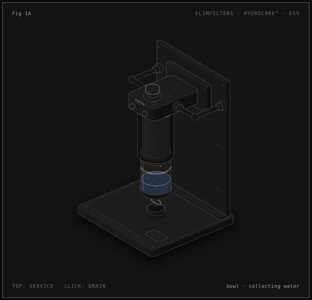
Reading the figure: Separator with reusable transparent bowl
- Head. The fixed head on the bracket carries the inlet and outlet, a hand primer pump to refill the circuit after service and a bleed screw to let the air out.
- Spin-on element. The fuel passes through the HYDROCORE™ separation element. Water drops form on the media and fall; moving the cursor sideways changes how much water the fuel carries.
- Transparent bowl. The bowl screwed under the element collects the water and the heavier residues. Because it is transparent, the level can be checked at a glance; the readout warns when it is near the limit.
- Drain. Clicking the figure, or pressing the space bar, opens the drain: the collected water runs into the catch cup and the level falls.
- Service. Moving the cursor to the top, or pressing E, runs the service: the element is replaced, and the same bowl is removed from the old element and fitted to the new one.
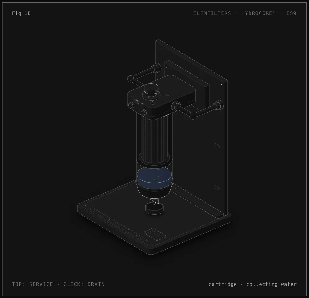
Reading the figure: Spin-on format with built-in drain
- Head. The same fixed head, with the inlet and outlet, the hand primer pump and the bleed screw.
- Spin-on cartridge. The HYDROCORE™ separation element and its sump are one sealed unit. The lower part is drawn in section so the inside can be seen.
- Sump. Separated water and residues settle at the bottom of the cartridge itself. With no transparent bowl, the level cannot be seen, so draining follows the maintenance routine.
- Built-in drain. Clicking the figure, or pressing the space bar, opens the drain at the bottom of the cartridge and releases the water into the catch cup.
- Service. Moving the cursor to the top, or pressing E, runs the service: the whole cartridge is replaced, drain included.
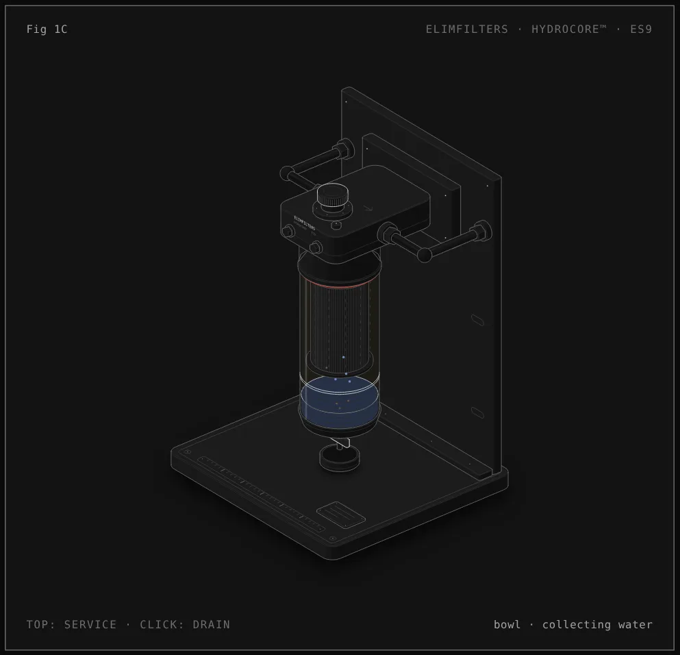
Reading the figure: Cartridge format: element inside a transparent bowl
- Head and shroud. The head and the metal shroud below it are permanent parts of the equipment. The bowl seals against the lip of the shroud.
- Element inside the bowl. The pleated HYDROCORE™ element sits inside a tall transparent bowl, so both the element and the collected water can be seen.
- Seal. The red ring marks the bowl seal. It has to be seated correctly at every service to keep the fuel in and the air out.
- Water and drain. Water and residues settle at the bottom of the bowl. Clicking the figure, or pressing the space bar, opens the drain into the catch cup.
- Service. Moving the cursor to the top, or pressing E, runs the service: the bowl comes down, the element is changed and the same bowl is refitted with its seal. Shroud and head stay in place.
What each component does
- HYDROCORE™ separation element
- The media that holds back the water droplets so they merge and fall, while the fuel passes through. It also holds particulate, so it loads over time like any filter.
- Head with primer pump and bleed screw
- The fixed part on the equipment, with the inlet and outlet. The hand primer pump refills the separator and the lines after service; the bleed screw lets the trapped air out.
- Transparent bowl
- Collects the separated water and residues and lets the operator see the level. In Fig 1A it is transferred to each new element; in Fig 1C it holds the element itself.
- Sump
- In the spin-on format, the lower part of the cartridge where the water settles. It is replaced with the cartridge.
- Drain
- The valve at the lowest point. Opening it releases the collected water; it must be closed again and checked for leaks.
- Bowl seal
- Closes the joint between the bowl and the element or shroud. A damaged or poorly seated seal lets fuel out or, on the suction side, air in.
- Metal shroud
- In the cartridge format (Fig 1C), the permanent housing under the head that the bowl seals against. It is not a service part.
Spin-on and cartridge formats
Spin-on with reusable transparent bowl (Fig 1A). The element is a spin-on, and a transparent bowl with the drain is screwed under it. The water level is visible. At service only the element is discarded: the bowl is cleaned, inspected and fitted to the new element with its new seal.
Spin-on with built-in drain (Fig 1B). Element, sump and drain form one sealed cartridge. Service is the simplest, since the whole unit is replaced, but the water level cannot be seen, so draining depends on the maintenance routine.
Element inside a transparent bowl (Fig 1C). The head and shroud are permanent; only the element inside the bowl is replaced. Both the element and the water can be seen, and less material is discarded at each service. It asks more of the technician: the bowl and its seal have to be clean, undamaged and seated correctly.
Which one applies. The format is set by the approved housing on the equipment. All three work on the same separation principle; what changes is how the water is seen, how it is drained and what is replaced.
Service sequence
- With the engine off, open the drain and release the collected water into a container. Dispose of it as fuel-contaminated waste.
- Confirm that the replacement is the HYDROCORE™ element approved for that non-turbine housing and format.
- Fig 1A: unscrew the element, remove the bowl from it, clean and inspect the bowl, and fit it to the new element with the new seal. Fig 1B: replace the whole cartridge. Fig 1C: lower the bowl, change the element, clean the bowl and refit it with its new seal.
- Check the bowl for cracks or damage before refitting it; a damaged bowl is replaced, not reused.
- Open the bleed screw and operate the hand primer pump until fuel without air comes out, then close the bleed screw, following the engine maker's procedure.
- Start the engine and check the bowl, the drain and every seal for leaks. Confirm the drain is closed.
Diagnosis in the circuit
Water comes back quickly after every drain
The separator is reporting what the fuel carries. Look upstream: tank condensation, water in deliveries, storage and transfer practices. Draining more often treats the symptom, not the source.
Dark sludge or slime at the water–fuel boundary in the bowl
A sign of microbial growth. It has to be treated in the tank and fuel system; changing the element alone will not remove the source.
Hazy fuel in the bowl but little free water at the bottom
The water may be dispersed in the fuel rather than free, and dispersed water does not settle in the same way. Review the fuel source and handling.
Water found downstream of the separator
Check whether the drain was overdue and the water reached the element's working volume, whether the correct element is fitted, and whether a seal lets fuel bypass the media.
Loss of power or hard starting with little water in the bowl
Consider particulate loading of the element or low-temperature waxing, and check for air entering at the bowl seal, the drain or the bleed screw.
02 /
Application Selection
A separator application must be evaluated from the incoming water condition, fuel flow, housing design, drainage method, bowl configuration and maintenance access. Effective operation depends on removing collected water before it reaches the element's working volume, maintaining intact seals and preventing contaminated transfer or storage practices from overwhelming the system. Inspection should differentiate free water, dispersed water, microbial debris and ordinary particulate loading because each condition changes the corrective action. Selection also has to preserve fuel supply under peak engine demand and remain compatible with the approved non-turbine separator housing.
Evidence Boundary
HYDROCORE™ applies only to approved standard non-turbine separator configurations. It does not establish one water-removal percentage, particle efficiency, capacity or drain interval for all products. Those values require validation for the individual element and assembly. FH and FG turbine-style architectures are explicitly outside this scope and are governed by TURBOCORE™.
02 /
Protection Systems
COMPLEMENTARY TECHNOLOGIES